GK-2000 (Dell R360 Server) Installation
Appliance: GK-2000 (Dell PowerEdge R360 – 10GbE)
1. Introduction
This document provides a step-by-step procedure to install the Xshield Gatekeeper software on the GK-2000 appliance, which is based on the Dell PowerEdge R360 server equipped with 10 Gigabit Ethernet (10GbE) interfaces.
The guide covers:
- Creating a bootable USB from the Xshield Gatekeeper ISO
- Installing the Gatekeeper software on the appliance
- Configuring BIOS boot settings
- Identifying and mapping 10GbE interfaces in Linux
- Configuring the Gatekeeper WAN (Upstream) interface
This guide is intended for system administrators and deployment engineers.
Once this installation is completed, please refer to the Xshield Gatekeeper Deployment Checklist for the checklist to ensure all pre-requisites are covered before the configuration.
2. Prerequisites
2.1 Hardware Requirements
- GK-2000 appliance (Dell PowerEdge R360)
- VGA monitor
- USB keyboard
- Bootable USB drive (minimum 16 GB)
- Network cables for WAN and LAN connectivity
Please note that the GK-2000 will have two 1 Gbe Ethernet Interfaces built-in on the motherboard and two additional 10 Gbe Ethernet Interfaces added on the hardware as a separate Ethernet Adaptor. The GK-2000 will use the two 10 Gbe interfaces for connecting to the Switch Ports. Please note that these interfaces must be detected and identified after the ISO image is loaded on the hardware.
2.2 Software Requirements
- Latest Xshield Gatekeeper ISO downloaded from the Xshield Platform
- USB image creation utility (for example: Balena Etcher)
Software Installation
Once the GK-2000 hardware is racked, the Xshield Gatekeeper software must be loaded on it. The current supported approach is to download the software from the Xshield portal and build a USB. Once that is done, the USB should be inserted in the front panel USB port of the appliance and set the BIOS settings to boot off the USB. This will automatically install the software on to the hardware. Please follow the below step by step instructions to execute this operation.
3. Connecting a Console to the GK-2000
Dell PowerEdge R360 Server
The first step in the installation process is to get console access to the appliance so that we can configure the hardware and install the software using the pre-loaded BIOS software.
This section describes how to connect a local console (monitor, keyboard, and mouse) to a Dell PowerEdge R360 server for the purpose of installing and booting the Xshield Gatekeeper appliance software.
The objective of this guide is to ensure:
- Correct physical cabling
- Proper identification of supported video ports
- Elimination of common console connection errors
3.1 Target Hardware
-
Server: Dell PowerEdge R360
-
Onboard Network Interfaces:
- 2 × 1 GbE (LAN on Motherboard)
-
Add-on Network Interface:
- 2-port 10 GbE adapter
3.2 Appliance Image Context
- Appliance: Xshield Gatekeeper
- Platform: ColorTokens Xshield
- Deployment Model: Bare-metal installation on physical server
3.3 Hardware Requirements
The following accessory hardware is required to establish a local console connection:
-
VGA Monitor
- Must support analog VGA input
-
USB Keyboard
-
USB Mouse
-
VGA (DB15) Male-to-Male Cable
- Standard VGA cable with male connectors on both ends
-
Power cables connected to the server
3.4 Dell PowerEdge R360 – Rear Panel Reference
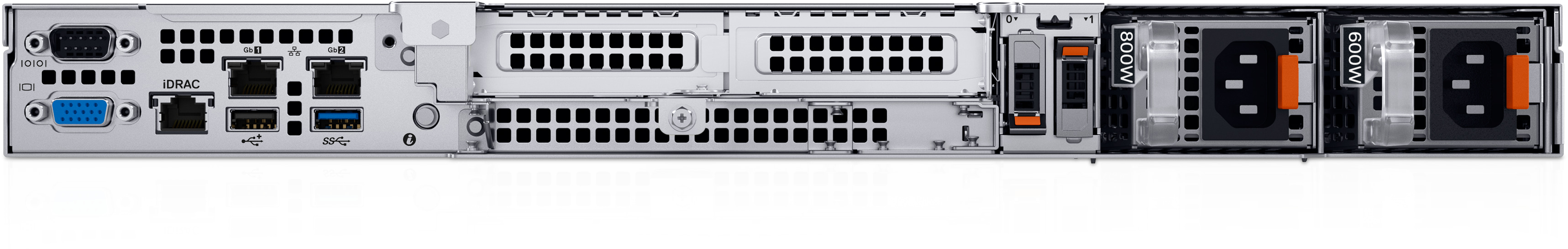
VGA (DB15) connection guidance The VGA (DB15) port is identified by the blue 15-pin connector located at the bottom-left of the rear panel in the image above. Connect the male-to-male VGA cable from this blue VGA port to the VGA monitor.
3.5 Important Note on Monitor Connectivity
Dell PowerEdge servers cannot be connected to a monitor using a DB9 cable.
- The DB9 connector is a serial (RS-232) communication interface
- It does not provide video output
- Local video output on the Dell PowerEdge R360 is supported only via the VGA (DB15) port
Attempting to connect a monitor using a DB9 cable will result in no display output during:
- Power-on self-test (POST)
- BIOS access
- Appliance boot or installation
Also, please note that even if you are using iDRAC to remotely manage the device to install the software, you must still use the VGA approach to first connect and set the iDRAC port's IP address (described later in the document).
4. Creating GK-2000 Image on USB
This section covers the process to create a bootable image of the GK-2000 software on an USB. This USB can then be connected to the appliance and update the BIOS settings to boot off the USB. This process then allows the GK-2000 software to be installed on the hard-drive of the server. Once that is completed, the BIOS setting is selected to boot off the software image on the HDD.
4.1 Downloading the Gatekeeper ISO
- Log in to the Xshield Platform.
- Navigate to: Sensors → Gatekeeper → Install
- Download the latest Gatekeeper ISO image.
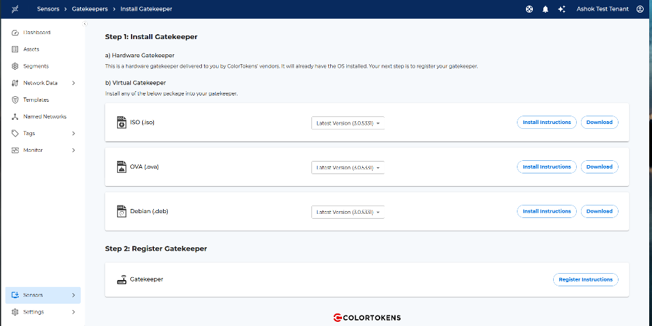
Xshield Platform UI showing navigation to Sensors → Gatekeeper → Install and the option to download the latest Gatekeeper ISO image.
4.2 Creating the Bootable USB
A bootable USB can be created by commonly available software such as Balena Etcher. The following screenshots show how to burn the ISO image on to a USB stick. For this, a USB stick of minimum 16 GB is required.
- Insert a USB drive (minimum 16 GB) into your workstation or laptop.
- Launch Balena Etcher (or an equivalent USB imaging tool).
- Select the downloaded Gatekeeper ISO.
- Select the target USB drive.
- Click Flash and wait for the process to complete.
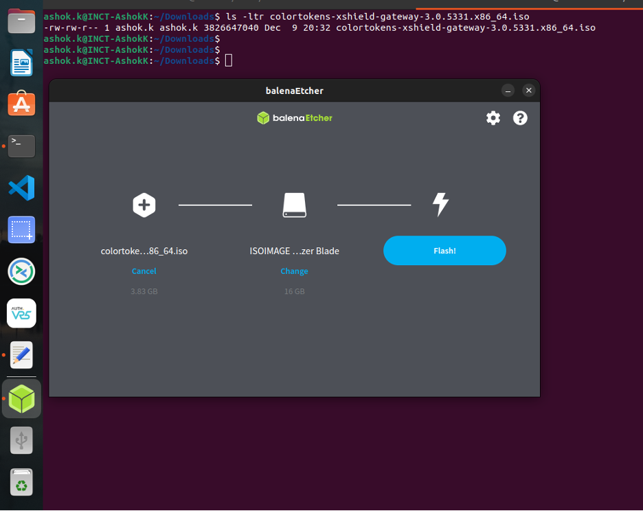
*Balena Etcher – Selecting the Gatekeeper ISO image and the target USB device *
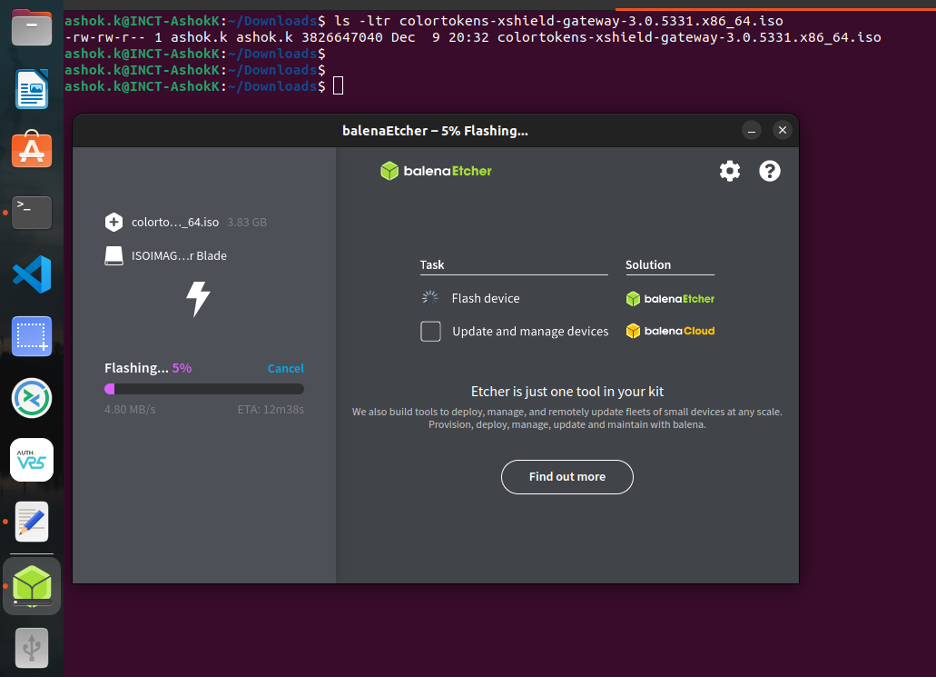
Balena Etcher – Flash in progress
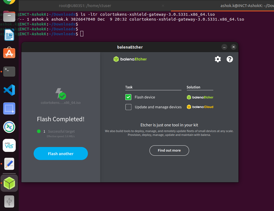
Balena Etcher – Flashing process completed
At this point, the USB drive has the Gatekeeper Image on it and is ready to be installed on the GK-2000 appliance as described below.
5. Software Installation
Now the Xshield Gatekeeper software is ready to be installed on the GK-2000 appliance.
5.1 Physical Connections
- Insert the bootable USB drive into the front USB port of the GK-2000 appliance.
- Ensure that the VGA monitor, USB Keyboard and Power Cables are all still connected.
- Power on the server.
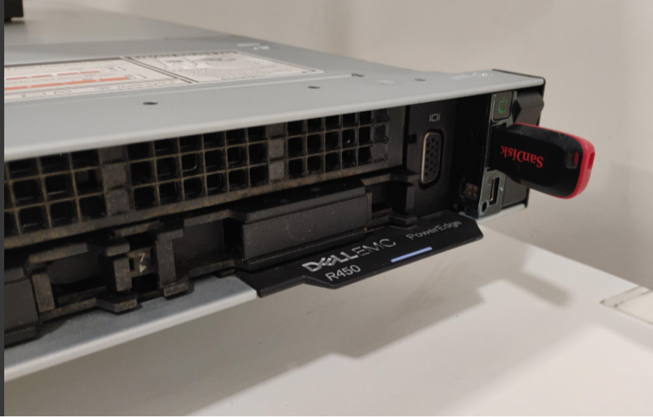
Front panel of Dell PowerEdge R360 with bootable USB inserted and power button.
5.2 Booting from USB
- During system startup, observe the Dell boot screen.
- Press F11 to enter the Boot Manager.
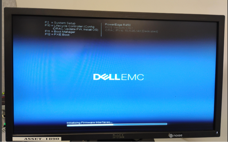
Dell PowerEdge R360 system boot screen during power-on self-test (POST).
-
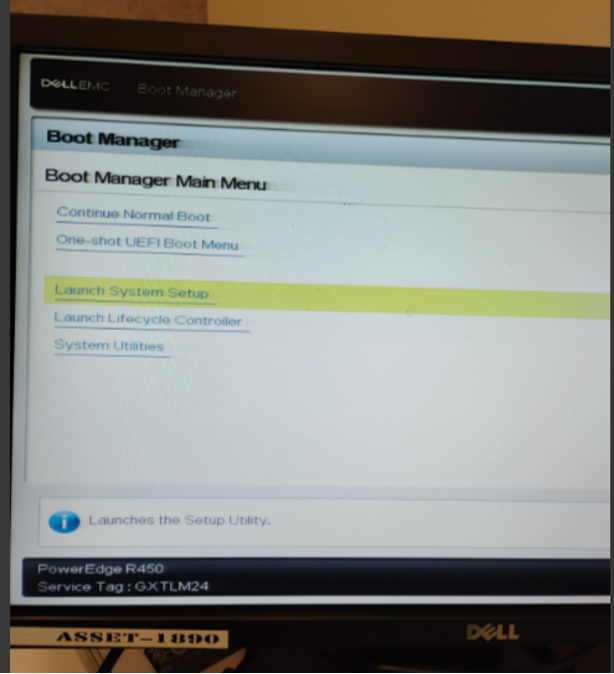
From the Boot Manager menu:
- Select Launch System Setup
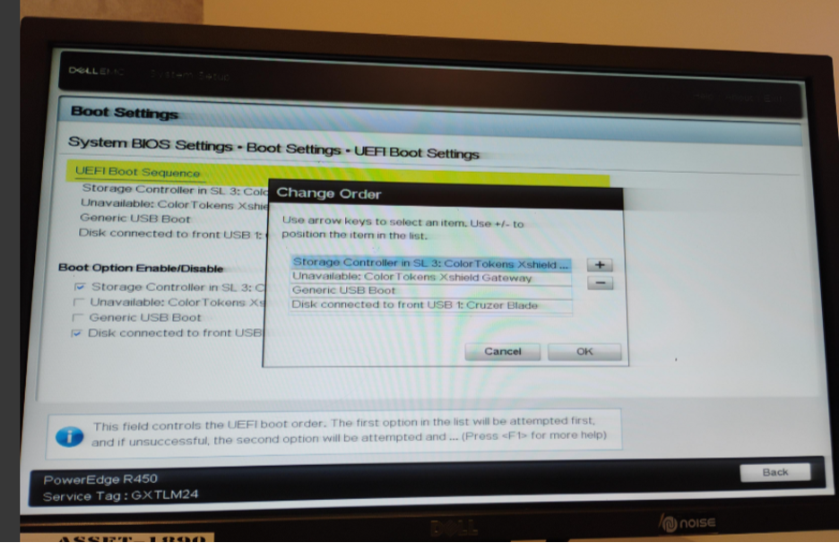
5.3 Configuring BIOS Boot Settings
-
In System Setup, select System BIOS.
-
Navigate to: Boot Settings → UEFI Boot Settings → UEFI Boot Sequence
-
Modify the boot order:
- Set Front USB Device as the first boot option.
-
Save changes and exit.
-
The system will reboot automatically.
5.4 Gatekeeper Installation
- After reboot, the GRUB menu appears.
- Select: Install ColorTokens Xshield Gateway (HDMI Console / VM)
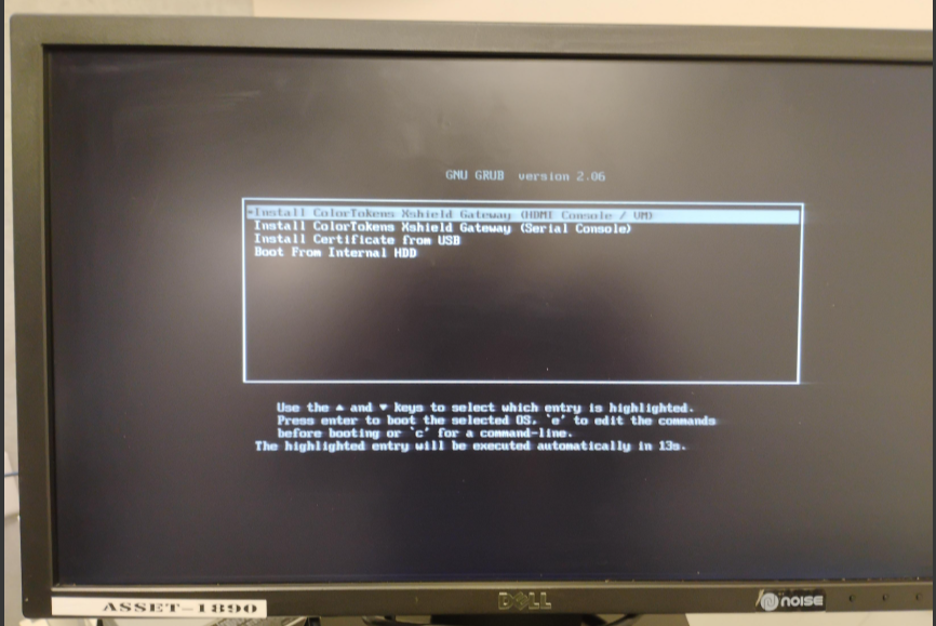
GRUB boot menu showing “Install ColorTokens Xshield Gateway (HDMI Console / VM)” option.
-
Disk selection screen:
- The installer auto-selects a disk (example:
/dev/sdb). - If the selected disk is correct, do not press any key (installation proceeds automatically after 30 seconds).
- To manually select a disk, press any key and specify the correct disk name.
- The installer auto-selects a disk (example:
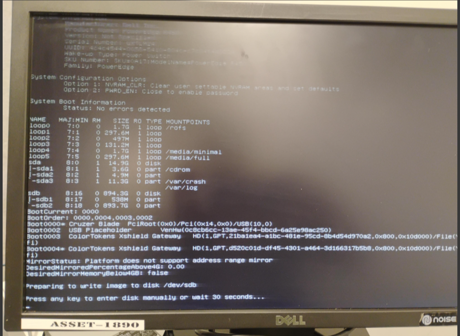
Gatekeeper installer disk selection and confirmation screen.
- The installer writes the base image to the selected disk.
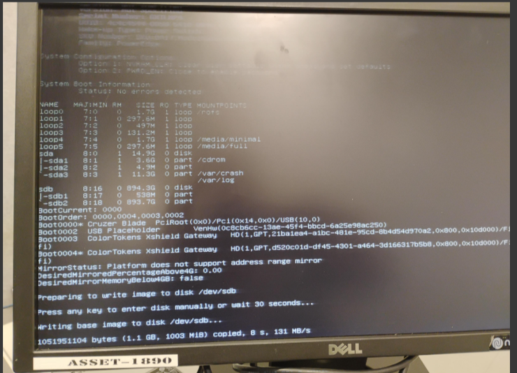
Gatekeeper installation progress showing base image being written to disk.
-
Upon completion:
- Installation completed message is displayed
- System automatically reboots twice
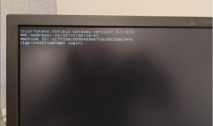
5.5 First Login
- After the reboots, a login prompt appears.
-
Log in using the default credentials:
- Username: admin
- Password: colortokens
-
You will be prompted to change the default password. This is a mandatory step.
** Also, do save this password somewhere safe as there is no password recovery mechanism available today. If password is forgotten, the appliance would have to be RMA'd or factory-reset and software reloaded.**
6. Detecting Network Interfaces
As mentioned earlier, your GK-2000 will have four Ethernet Interfaces. Two of them (typically seen on the left side) are the on-chip 1Gbe interfaces. The GK-2000 comes installed with two 10Gbe interfaces as a separate NIC card (plugged in the middle of the back panel). The two 10Gbe interfaces are what will be used by the GK-2000 as the upstream and downstream ports. The upstream port will be the first from the left and the downstream port will be the one adjacent to it.
** The ordering of the Upstream and Downstream ports are important as their 'context' is mapped into the Gatekeeper software**
You must exit the Gatekeeper configuration menu to first identify and configure these 10Gbe interfaces before continuing with configuration of the appliance.
After password change, the Gatekeeper configuration menu appears.
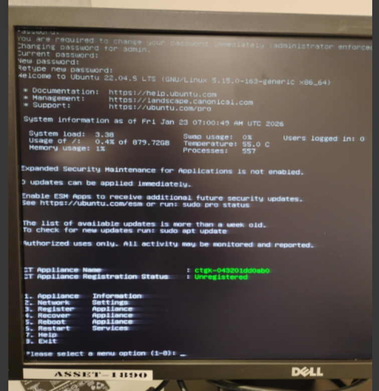
-
Exit the menu by selecting Option 8 (Exit).
- This step is mandatory to identify interface names before configuration.
6.1 Identifying Interface Names
-
Switch to root shell:
sudo su -
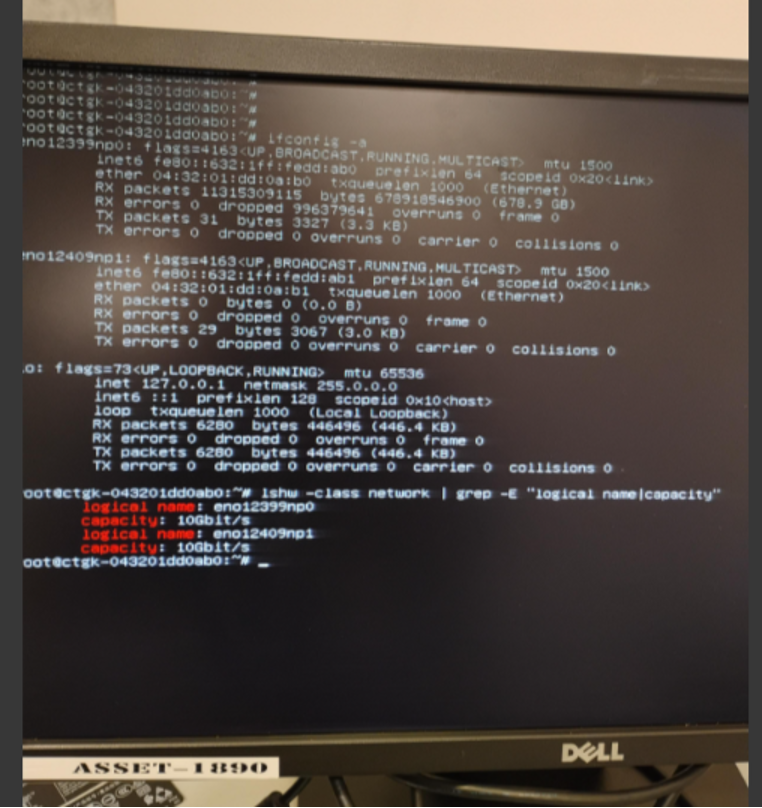
Display all interfaces:
ifconfig -a -
List network hardware details:
lshw -class network | grep -E "logical name|capacity" -
Note the interface names corresponding to 10GbE ports.
6.2 Mapping Physical Ports to Linux Interfaces
Usually, Dell numbers the ports from left to right per adaptor. However, Linux does not use the Dell's port numbering but uses the hardware information to build its logical interface names
How Linux sees those ports (OS view)
Linux does not care about Dell’s printed port numbers.
Instead, Linux names interfaces based on:
- PCI bus location
- Device type
- Firmware/BIOS information (SMBIOS + ACPI)
That’s why you see names like:
eno1
eno2
ens3f0
ens3f1
enp2s0
6.2.1 Modern predictable naming (systemd/udev)
| Prefix | Meaning |
|---|---|
enoX | Onboard NIC (embedded on motherboard) |
ensX | Hot-plug PCI slot |
enpXsY | PCI bus/slot based naming |
f0 / f1 | Port number within the NIC |
Example:
ens3f0  → NIC in slot 3, function 0 (Port 1)
ens3f1  → NIC in slot 3, function 1 (Port 2)
👉 This is the key link to Dell port numbers
6.2.2 How to map Dell Port # → Linux Interface (practical steps)
Method 1: ethtool (most reliable)
ethtool -i ens3f0
Output:
bus-info: 0000:03:00.0
Then:
lspci -nn | grep 03:00
This tells you:
- PCI slot
- Which NIC card
- Which port (function
.0vs.1)
Method 2: Blink the port LED (best in data centers)
ethtool -p ens3f0 10
→ The physical port LED blinks for 10 seconds
That port = that interface. No guessing.
Method 3: MAC address correlation
- Read MAC printed on NIC or iDRAC
- Match it in Linux:
ip link show
Method 4: Loopback method
- Connect both 10GbE ports to a switch or loop them back.
- Disconnect one cable at a time.
- Observe console logs to identify which interface goes DOWN.
- Map each physical port to its corresponding Linux interface name.
Once the interface names are identified, write it down so that it can be used to configure the WAN and LAN interfaces of the Gatekeeper in the next step.
7. Network Configuration Using ctconfig
7.1 Interface Assignment
-
Connect the mapped physical interfaces:
- First 10Gbe port (from left): WAN (Upstream)
- Second 10Gbe port: LAN (Downstream)
-
Start the configuration utility:
sudo ctconfig
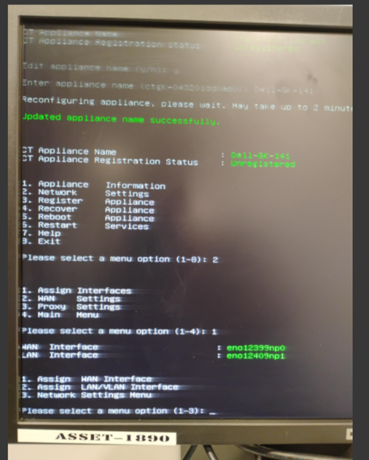
7.2 Configure Appliance Name
- Select the option to configure the Appliance Name.
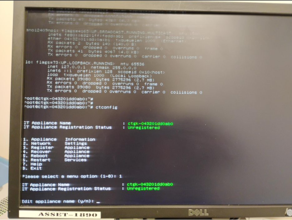
ctconfig utility – Appliance name configuration screen.
7.3 Configure Network Settings
-
Select Option 2 – Network Configuration.
-
WAN and LAN interfaces are auto-selected:
- First interface → WAN (Upstream)
- Second interface → LAN (Downstream)
-
Verify interface selection carefully.
-
If incorrect, use Assign Interface option to manually select the correct interfaces.
7.4 Configure WAN Interface
We will add a static IP address to the WAN interface of the GK-2000 appliance.
-
Configure the WAN interface with:
- Static IP address
- Subnet mask
- Default gateway
-
Save the configuration.
-
Exit the ctconfig utility.
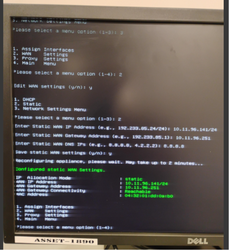
ctconfig utility – WAN (Upstream) interface IP address and default gateway configuration screen.
8. Verification and Next Steps
-
Verify connectivity by accessing the Gatekeeper via SSH using the WAN IP address.
-
Log in and relaunch:
sudo ctconfig -
Proceed with remaining configuration steps, including:
- Gatekeeper registration
- Policy and integration setup
9. HA Pair
If you are configuring a set of GK-2000 for High Availability or for load balancing, repeat the same steps on the 2nd GK-2000
10. Summary
The Xshield Gatekeeper software is now successfully installed and reachable over the WAN interface on the GK-2000 appliance. The system is ready for registration and further integration into the Xshield security platform.
Please refer to the Xshield Gatekeeper Deployment Guide for configuration and management of the GK-2000 appliance.