Deployment Guide
Background
ColorTokens Xshield gives you a single-pane-of-glass approach to manage micro-segmentation for all types of assets : data center servers, cloud workloads, containers, user endpoints, Internet-of-Things, Operational Technology devices, and even legacy operating system devices.
The Xshield platform employs agents or appliances to enforce detailed policies for micro-segmentation. While agents necessitate deployment on each protected system, the Xshield gateway appliance seamlessly integrates into existing networks with minimal disruption. Positioned within the subnet, typically a LAN/VLAN, the gateway appliance functions as a distinct network component. It operates through two networks: an upstream network for inbound and outbound communication, and a downstream network to connect all the devices the gateway appliance is positioned to secure. Once activated within the subnet, the gateway appliance assumes the role of gateway for all the devices in your downstream network.
Deploying Gateway Appliance
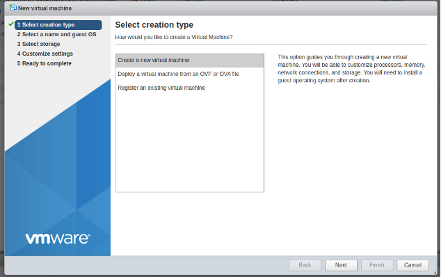
This gateway appliance can be deployed either as a hardware or virtual appliance, with both options utilizing the same Xshield gateway appliance software. The difference lies in the execution environment: In the virtual appliance this software runs within a virtualization environment such as VMware, while in the case of a hardware appliance, this is a physical appliance such as the one shown in the picture below. The hardware appliance can either be a ColorTokens Xshield gateway appliance box such as the one below or compatible hardware on amd64 architecture which can run ubuntu 22.04. There are 3 modes for appliance install
-
Hardware Xshield gateway appliance from ColorTokens
-
Virtual Appliance in ESXi or other virtualization platform using either OVA or ISO image
-
Customer hardware on amd64 architecture capable of running ubuntu 22.04 with 2 or more network interfaces. Hardware needs to be flashed using ISO image.
Note: In all deployment methods proceed with section “Configuring Gateway Appliance” once the Hardware / Virtual appliance is setup with appropriate ISO/OVA image
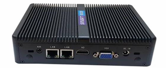
Figure 1 Gatekeeper Agentless Hardware Appliance for IOT and OT Applications
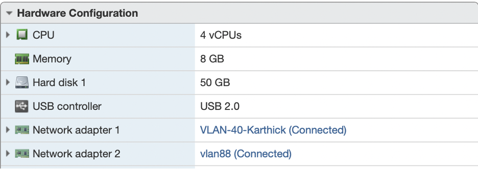
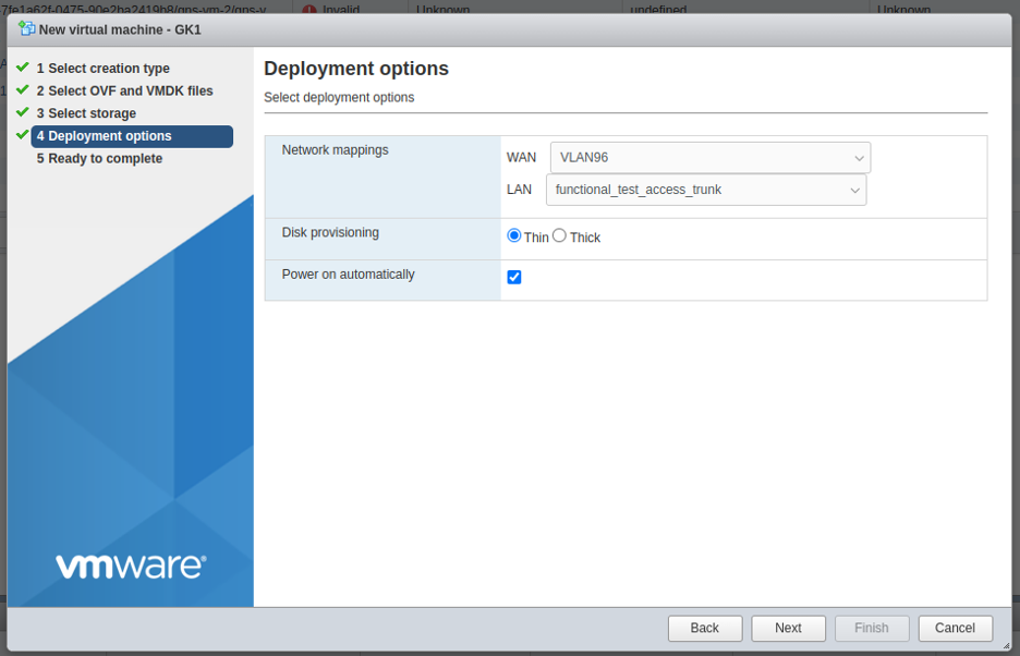
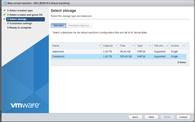
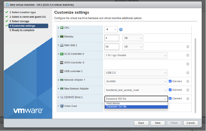
Figure 2 Gatekeeper Agentless Virtual Appliance for IOT and OT Applications
Shown above is a sample configuration of a virtual gatekeeper appliance running on VMware ESXi 6.5.
Note: Two network adapters are required—one for the upstream network and the other for the downstream network. The gatekeeper appliance can be set up in either standalone mode or high availability mode. In the case of a high availability (HA) configuration, two gatekeeper appliances operate in active/standby mode. Should any issues arise, the active gatekeeper appliance automatically switches over to the standby appliance.
Appliance Setup and Registration
Appliances can be deployed either as standalone or an HA pair. When deploying as an HA pair, each appliance must be individually registered to the Xshield console. To register appliances, follow the steps below:
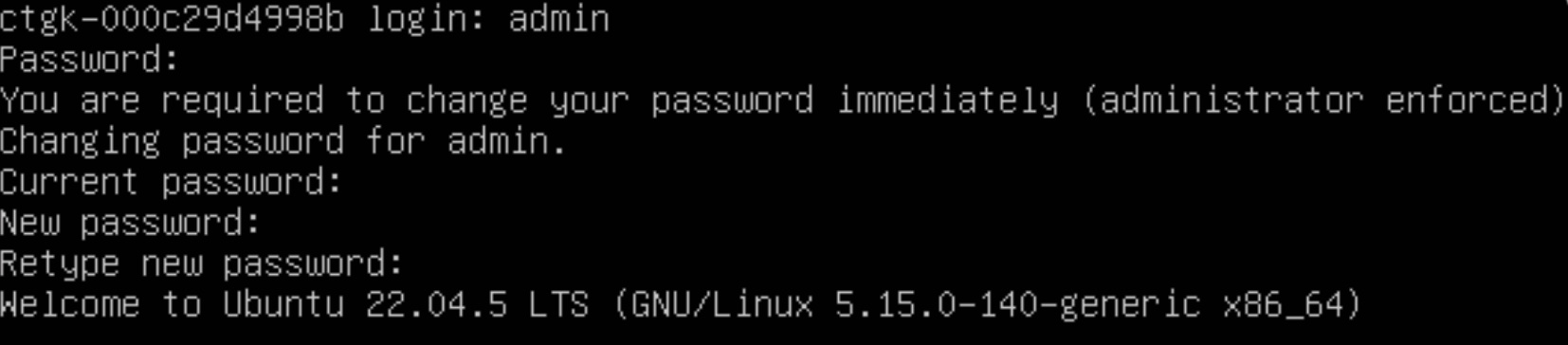
- Bootup and login Hook up a console cable to the box and boot up the gatekeeper (hardware gatekeeper). Login to the gatekeeper to see CLI options using the username "admin" and password as "colortokens" (The same step can be done via ESXi console for virtual appliance) You will then be required to enter a complex password consisting of:
- 8 or more characters
- 1 Upper case
- 1 Lower case
- A number
- A special character
-
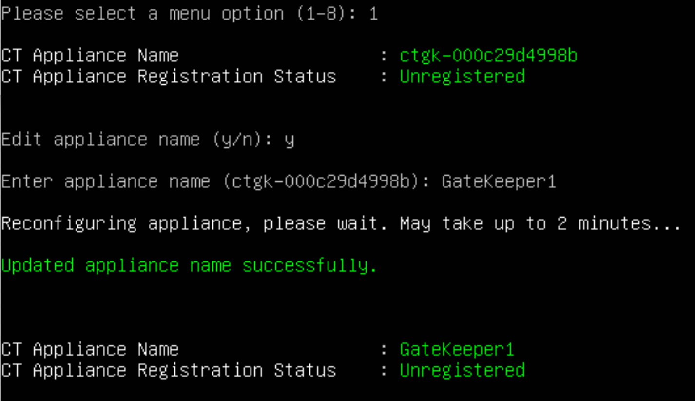
Enter gatekeeper name When you start the CLI, a default gatekeeper name appears. It is highly suggested you set a meaningful gatekeeper name. Select 1 follow the prompts and enter a name
-
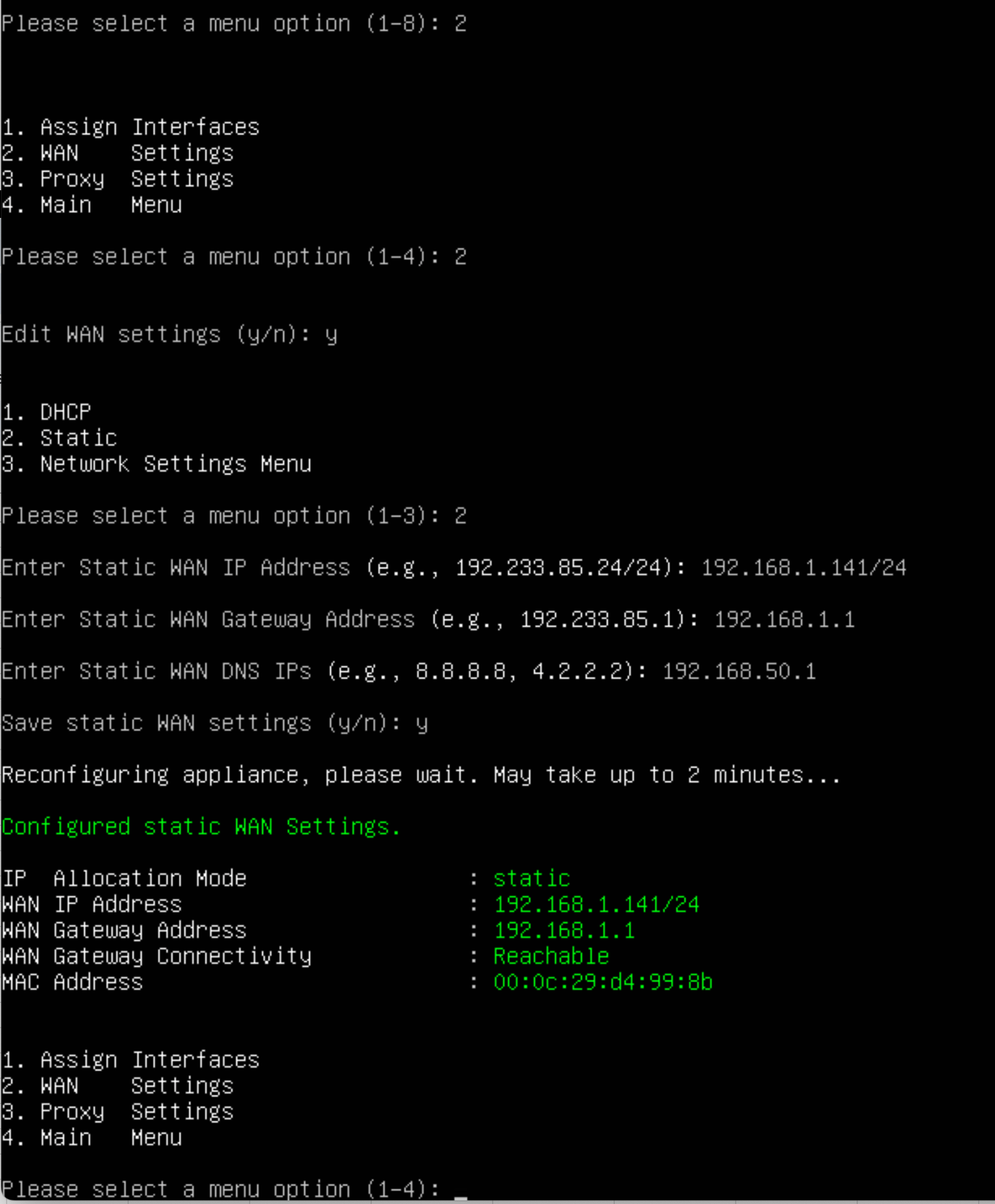
Setup WAN interface Next, you will see some information about your gatekeeper. Configure the WAN or unprotected interface of the gatekeeper. This is also the interface that can reach the management platform. You need to know:
- IP address and Netmask
- Gateway Address
- DNS Server (if Saas)
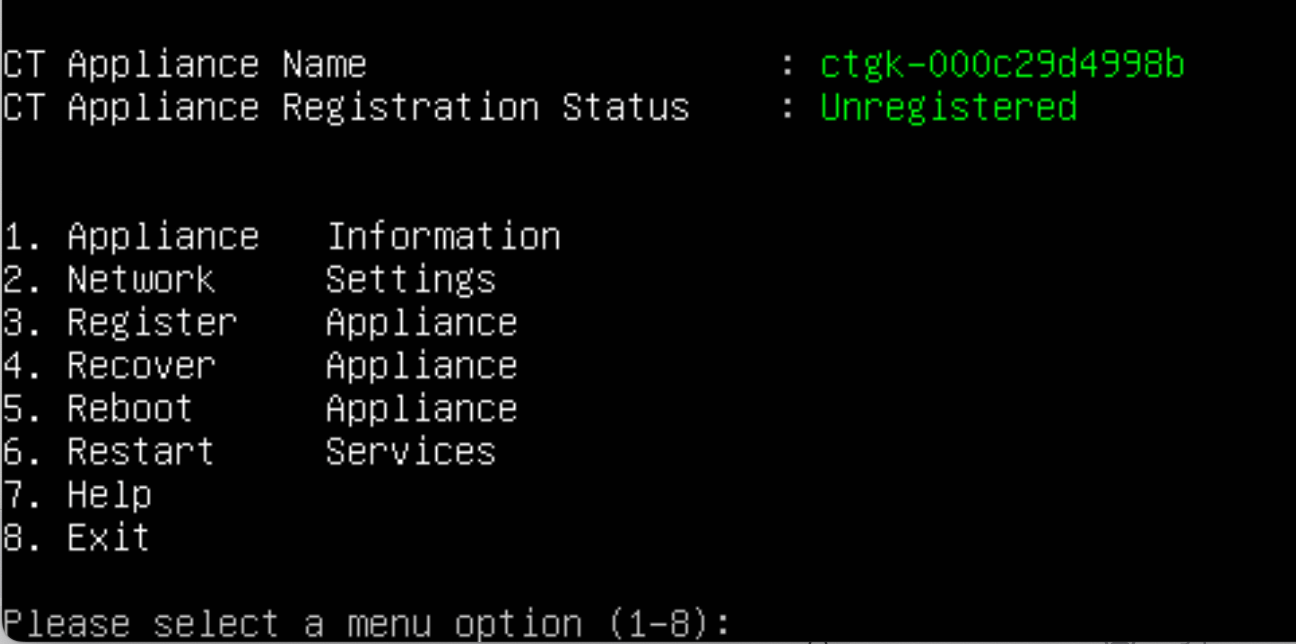
Once the gatekeeper is configured and the displayed information is correct, you can register it with the management platform. Select option 3 from the Main Menu to register the gatekeeper.
Register with Activation Code
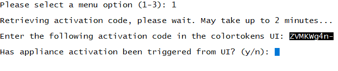
- Select Option 1 to Register Appliance with Activation Code.
- Copy the activation code from the CLI (Selected text as in below image)
- Login to Cluster and select required tenant
- Go to Sensors and then select Gatekeepers Option (Bottom left corner of the page as shown in below image)
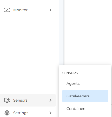
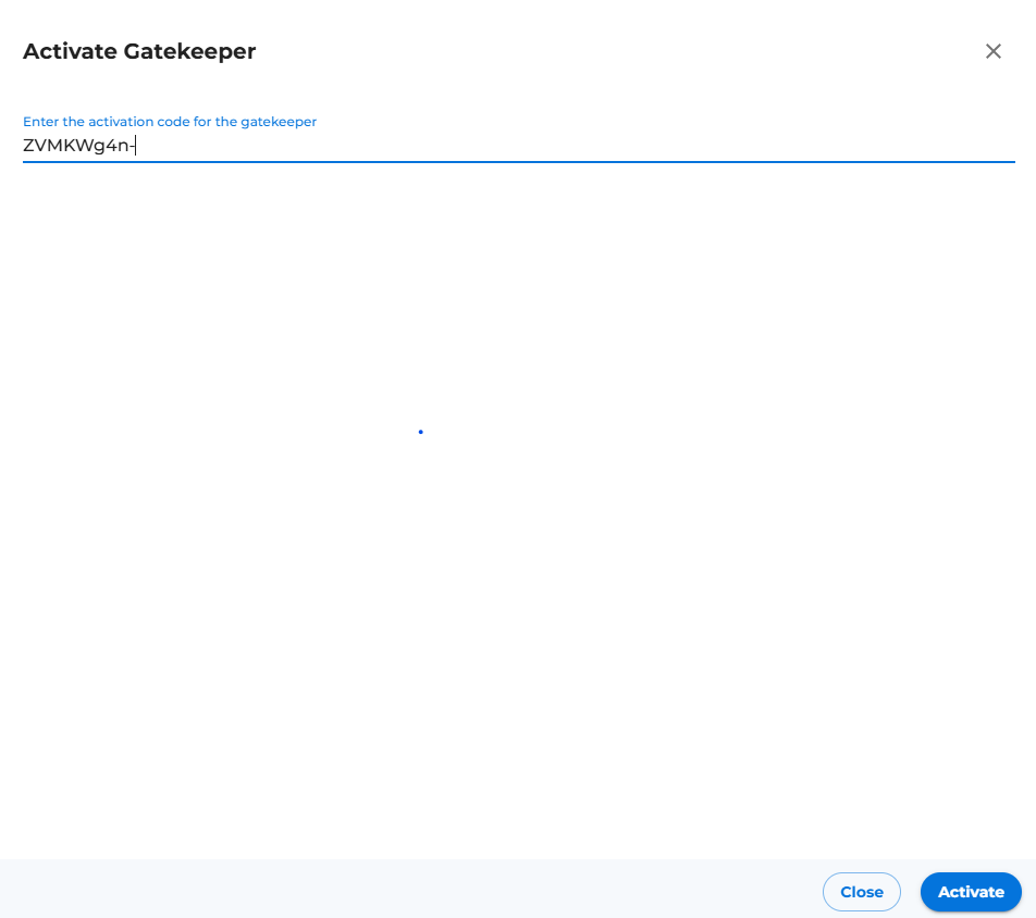
- Click on Activate button (Top Right corner of the Gatekeepers page as shown in below image), a new window will open up asking to ente the activation code.
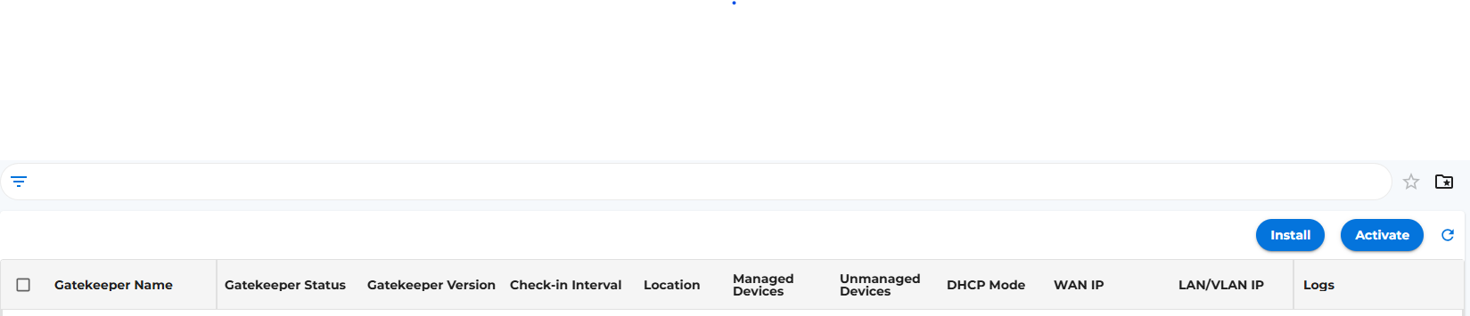
- Provide copied activation code from Step 2 and click on activate button (Placed at right bottom corner of the new drawer opened after Step 5 shown in below image).
- We see appliance name is detected and activation progress indication will be seen as shown in below image
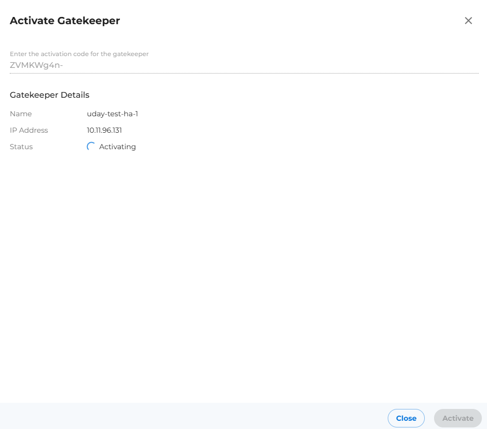
- Enter y as input in appliance activation CLI as activation triggered from UI
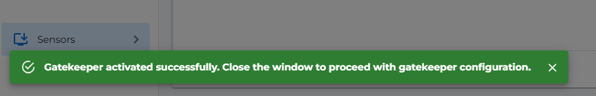
- Wait for the activation to complete, Message will be shown in left bottom corner as shown in below image.
- Close the drawer and refresh the page to see the gatekeeper in the list. Go to gatekeeper options to configure the gatekeeper.
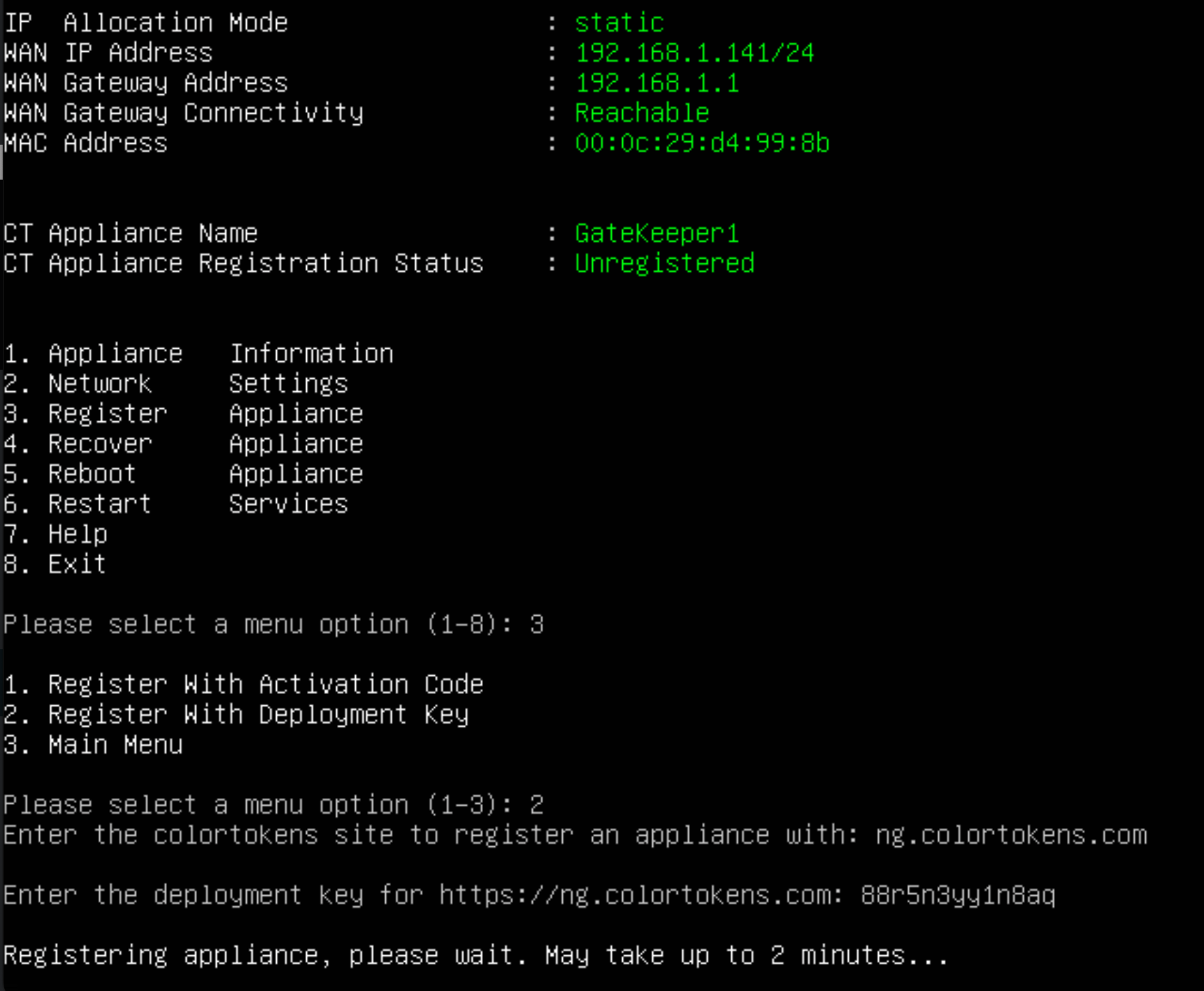
Register with Deployment Key
- Copy the deployment key from Colortokens portal by clicking on [Gatekeeper (Left menu bar) --> Install Gatekeeper --> Register Instructions ] and paste it into the CLI.
- Initiate activation and wait for process to complete.
- Verify your gatekeeper is registered on the Gatekeeper List. If its ready, go ahead and configure the gatekeeper.
Perform the same steps above for the second appliance (in the HA pair).
At this point both appliances should be able to communicate to the Xshield console and should be visible on the platform, as shown in picture below:
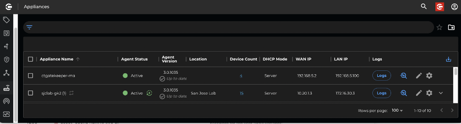
Figure 3: Gateway Appliance list in Xshield Console
In Figure 3, selecting the Appliance Icon from the left menu bar displays the list of appliances in the User Interface (UI). Newly added appliances will appear as depicted above. Configuration of the appliance is conducted by clicking on the gear icon located on the right side of the corresponding row. Selecting the configure icon opens the appliance configuration UI, allowing users to configure the appliance directly from the console.
Appliance Configuration UI
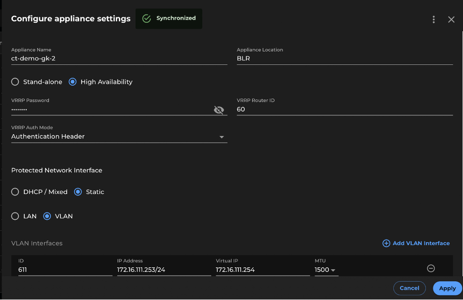
Figure 4: Gateway Appliance Configuration UI in Xshield Console
The appliance configuration UI allows the appliance to be configured as a Standalone or a HA Appliance.
The appliance has following configuration options.
Standalone Mode
If configuring a standalone appliance you would only configure one appliance.
High Availability (HA) Mode
When setting up an HA appliance pair, the process involves configuring each appliance individually. You begin by configuring the first appliance through the configuration screen, then repeat the same process for the second appliance. Initially, you configure the primary appliance, and subsequently designate the other gateway appliance as the standby.
DHCP can be enabled or disabled, if set to static mode. If DHCP is enabled, the lease time DHCP start and end IP will need to be configured. Also, DHCP can be either in server or a relay mode. In server mode, the gateway appliance will act as the DHCP server. However, in relay mode the gateway appliance acts as a DHCP relay and will communicate to the specified DHCP server to relay the DHCP request and responses.
The IP Address in the protected network interface section is that of the appliances' LAN or downstream interface. It would need to be configured, to be different for the primary and standby appliance in case of HA.
In the WAN section you need to specify the IP address of the appliance’s WAN interface as well as the gateway IP on the WAN side interface. Lastly, you also need to specify the DNS IP address for the WAN interface.
For an HA appliance additionally, you need to configure a virtual IP and Peer IP for both WAN and LAN interface. The Virtual IP represents the common IP assigned to the active appliance among the HA pair for WAN and LAN respectively. Similarly the Peer IP is the IP for the other appliance, i.e., Primary will use Standby IP as the peer IP and vice versa.
Click on "Apply", once the above settings are configured. This would apply the configuration changes on the appliance.
Note:
While undergoing the configuration process described above, the
appliance UI will indicate an 'In Progress' state at the bottom. Once
the configuration is successfully applied, the UI will display
'Synchronized'. Conversely, if there is a failure, it will show
'Failed'. In case of failures, you can review the Logs to diagnose the
issue.
In the context of HA, after completing the configuration for the primary appliance, proceed to configure the standby appliance. Once both appliances in the HA pair are configured and operational, you will observe both appliances listed in the appliance list UI (refer to fig 5)
Using the Static Vs. DHCP Mode
If using static mode, all static devices' network configuration will need to be modified to specify the gateway IP and netmask for the static device. Gateway IP should be set to the LAN VIP of the gateway appliance. The netmask should be set to /32 or 255.255.255.255 in the devices network settings. This will ensure the static IoT / OT devices send all their traffic via the gateway appliance.
If using DHCP relay/server mode, the routing of traffic via the gateway appliance is done automatically by the appliance as part of the DHCP protocol. For DHCP devices, disconnect and connect back the devices so they can get a new DHCP lease from the gateway appliance if using DHCP server mode. If using DHCP relay mode, the device will automatically renew its address and should not need to be reconnected.
In the case of DHCP server / relay mode it is important to ensure that the Gateway appliance is the only DHCP relay / server in the entire subnet. DHCP is a broad cast protocol and it necessitates only one DHCP server / relay in a subnet.
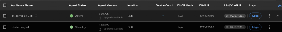
**Figure 5: Gateway Appliance list showing HA appliances **
Virtual Appliance Installation (OVA)
-
Need ESXi 6.5 or above.
-
Determine the networking details for the WAN (upstream) interface.
Here is a sample networking configuration for the WAN interface. This configuration must be functional to enable communication between the appliance and the Xshield platform and the same can be edited from the Xshield console.
- Setup Disk and network interfaces for VM in ESXi (see section below “Increasing size of the disk and configuring network”)
WAN Details
Subnet: 10.1.60.0/22
IP Address: 10.1.63.249
Gateway IP: 10.1.60.1
DNS Address: 10.1.3.250, 10.1.2.11
-
Download OVA image for a gatekeeper appliance from the Appliance Downloads page of the Xshield Console.
-
Create a Virtual Machine (VM) out of the OVA image on ESXi server – named gatekeeper1, gatekeeper2. (you can name it as per your choice)
-
In ESXi Server check following:
6.1. Ensure the two ports WAN (ens160) and LAN (ens192) of the Primary Appliance are connected to the WAN and LAN network/virtual port group respectively. LAN corresponds to the segment which is going to be controlled by the gatekeeper.
6.2. Ensure the two ports WAN (ens160) and LAN (ens192) of the Standby Appliance are connected to the WAN and LAN network/virtual port group respectively.
6.3. Ensure that the default VM settings such as RAM size (default 8GB), # of CPU cores (default 4), or HD size (default 40GB). Note: the file system will automatically expand to the size configured here when the image is first booted up.
6.4. Power ON the VM in ESXi console
Increasing size of the disk and configuring network interfaces
- Select WAN and LAN virtual port groups** **
- After creating and power on the VM which was created from OVA -
disk will be of size 4.3 GB only , user needs to increase the size by performing following steps : power off VM , edit VM setting and set the size to 50GB ( as per need )
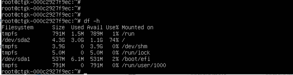
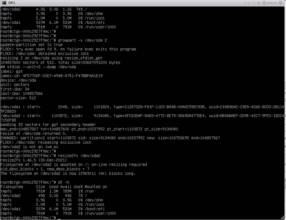
- power on and execute following from the VM console:
growpart -v /dev/sda 2 (space between /dev/sda and 2)
resize2fs /dev/sda2
Appliance Installation using ISO Image
This section describes how to utilize the iso image from the appliance
download page of the Xshield console to setup a HW appliance.
ISO can also be used to boot Appliance VM on Esxi ,virtual box etc
instead of OVA based appliance deployment which was described in
previous section.
Note that only amd64 based hardware capable of running ubuntu linux 22.04 is supported with this iso image.
Create Bootable USB from ISO
To write the raw iso image directly to a UAB drive on windows you can use the media creation tool. For Linux / mac OS system you can use a simple command line utility to write the iso image to USB drive or use applications like balenaEtcher
-
Determine the usb device using below command:
**$ sudo lsblk ** -
If the usb device is /dev/sdb, then you would use below command to burn the iso image to the drive. Note, that this assumes the iso image is in current directory.
**sudo dd bs=32M if=ctgatekeeper-base.iso of=/dev/sdb **
Boot HW appliance from the Bootable USB :
- Connect to the appliance serial console (using minicom / TeraTerm / etc) or connect HDMI monitor and keyboard and power it up. Go into the boot configuration menu (typically F11) and select the USB stick as the boot device.
- Next, the bootloader will prompt you with some options. Select “Install ColorTokens Xshield Gateway” from the menu and press enter.
- The Live image will boot the kernel from the USB stick and should automatically begin the process of overwriting the internal hard drive (/dev/sda).
- When the process is complete, you will be prompted to remove the USB stick and to press any key to reboot.
- Now the appliance will boot from the internal HDD, Once the OS is up login prompt will be shown indicating the Xshield gateway version: 3.0.xxxx , MAC address, Machine ID.
- The default admin user is “admin”. The password is “colortokens”.
The admin account is configured to expire this password, so it must be changed immediately upon logging in for the first time.
Once the system is up and running follow the procedures in the “First appliance install” or “Second appliance install” section as appropriate.
Booting Appliance VM on ESXI using ISO
- Create new VM:

- Select 4 CPU, 8GB, 2 Network Adapters, ISO file
- Finish creating the VM and power on the VM.
After this follow the same steps as mentioned in booting HW appliance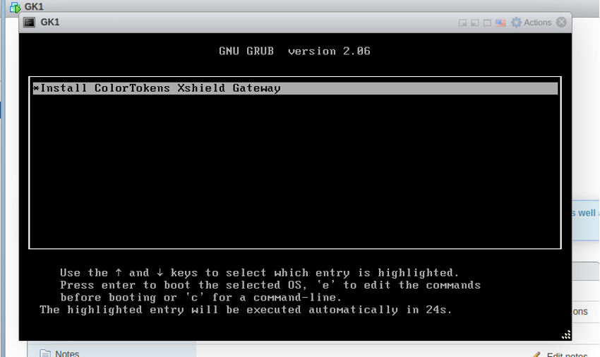
Note 1: If Following error is observed -”Cannot continue installation -
system is not configured with UEFI boot”
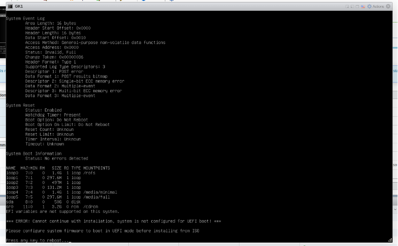
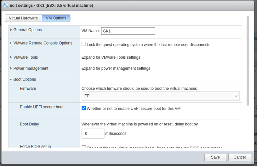
Power off the VM and set UEFI boot:
Note 2:
If the installation process is not able to identify the DISK to be
selected for writing.
The installation process will list down the system information and
indicate which disk is selected for writing, the user will be prompted
to press any key to select the disk manually.
User should key-in the disk name as /dev/xxx .
 After this installation process will start writing to the disk
/dev/sda
After this installation process will start writing to the disk
/dev/sda
 After this step – its same as HA appliance installation, VM will boot,
and login prompt appears. Login and use ”ctconfig” utility to configure
After this step – its same as HA appliance installation, VM will boot,
and login prompt appears. Login and use ”ctconfig” utility to configure
Decommission Appliance
Appliances can be decommissioned from the UI or from the console using ctconfig utility. An appliance can be decommissioned from the Xshield Portal even if it is no longer on the network. Decommissioning an appliance will attempt to first uninstall the appliance (if connected), preserving the WAN connectivity and if not connected will proceed with removing all devices, traffic, templates and other data in the console related to the appliance. This is a destructive operation and cannot be undone.
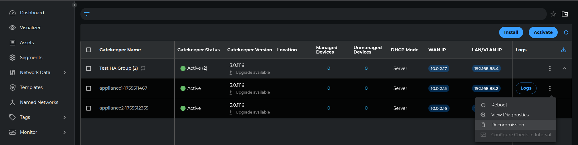
From UI
To decommission the appliance, navigate to the Gatekeepers list page in the UI and select the target Gatekeeper from the list. Click the Action menu on the right side and choose the "Decommission" option.
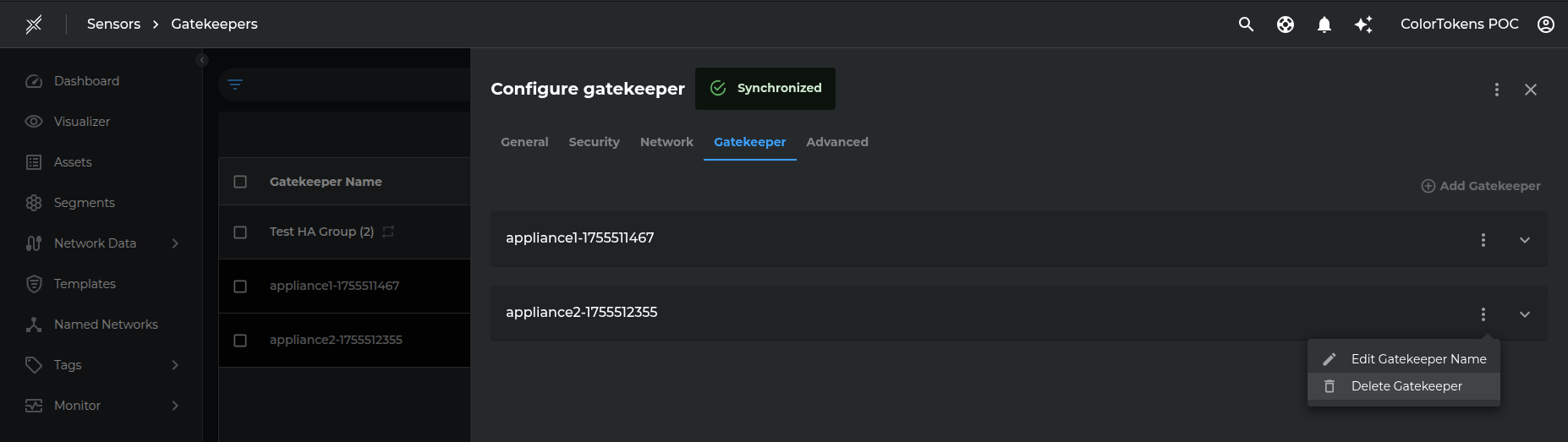
If the Appliance is part of a High Availability (HA) group, it can also be decommissioned through the HA group's Configuration UI by navigating to the Gatekeeper tab and selecting the delete option for the specific appliance.
From the console using ctconfig utility
Appliances can be decommissioned from the console using ctconfig utility as follows:
- Login to the appliance console as root.
- Run the following command:
ctconfig
- Select the option 3 to decommision the appliance.
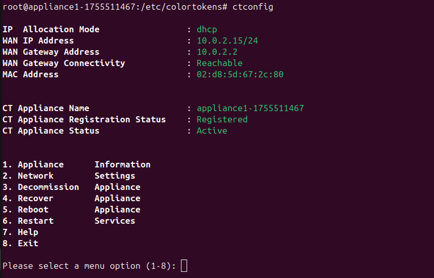
- When prompted with "Are you sure you want to decommission your appliance (y/n)", type
yand press Enter.
Appliance installation on Custom Hardware using Xshield debian package
For custom hardware based appliance users need to use compatible hardware running amd64 architecture with multiple network interfaces, sufficient disk, cpu and memory. In this case users can use the ebian pkg(colortokens-xshield-gateway-3.xxxx.x86_64.deb) to install the appliance software on the custom hardware.
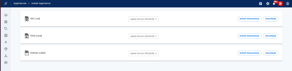
-
User can download the latest pkg from the appliance download page.
-
VM or HW appliance should have the WAN interface configured. Here is a sample netplan configuration file:
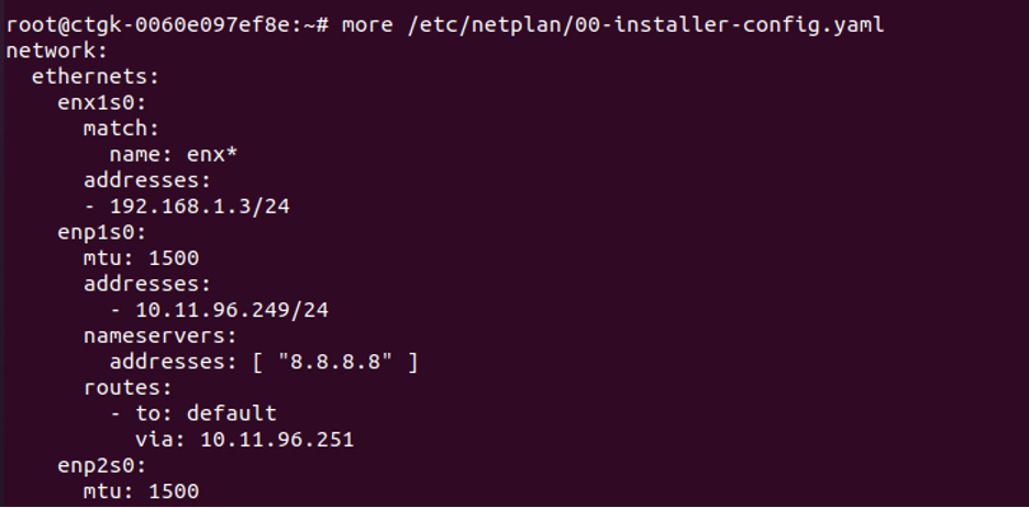
-
Netplan should be applied and should look like below when running ipconfig command:
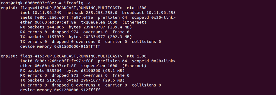
-
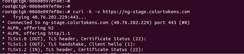
Gatekeeper should have access to backend - https://xxxx.colortokens.com You can confirm network access by executing
- curl -k -v https://ng-stage.colortokens.com
-
DNS server should be configured.
-
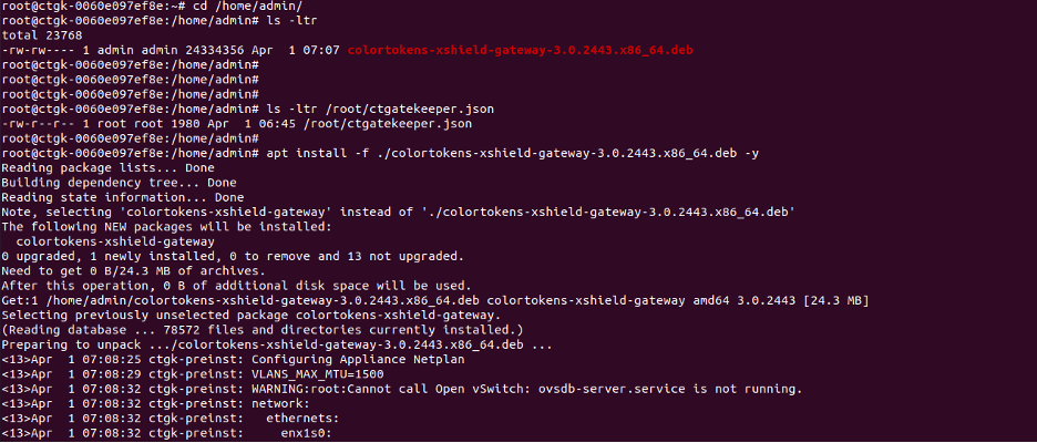
Valid ctgatekeeper.json file has to be placed in /root directory of the appliance.
-
Install the gatekeeper by running the apt install command as below: